
Honeywell 10101/2/1 Fail-Safe Input Module
The Honeywell 10101/2/1, also cataloged as the 10101/2/1 Fail-Safe Digital Input Module, operates as a dedicated hardware component for 24 VDC discrete signal acquisition and safety switch contact monitoring within Honeywell Fail Safe Controller (FSC) and Safety Manager platforms.
Hardware Specifications
| Parameter | Specification |
|---|---|
| Model | 10101/2/1 |
| Brand | Honeywell |
| Origin | Netherlands |
| Weight | 0.2 kg (Shipping Weight: 2 kg) |
| Dimensions | 4 TE, 3 HE (4 HP, 3U Eurocard form factor) |
| Operating Temp | 0 deg C to +60 deg C |
| Logic Power Consumption | 5 VDC at 8 mA (Backplane) |
| Field Power Consumption | 24 VDC int. 110 mA / 24 VDC ext. 110 mA |
| Allowable Power Ripple | < 0.5 Vp-p (0-360 Hz on 5 VDC line) |
| Channel Count | 16 discrete input channels |
| Input Thresholds | HIGH > 15 VDC; LOW < 9 VDC (I < 2 mA) |
| Max Input Voltage | 36 VDC |
| Input Current Nominal | 7 mA at 24 VDC |
| Input Delay Time | Typically 10 ms |
| Firmware Compatibility | Software versions >= 3.00 |
| Approvals & Certifications | CE, TUV, UL |
Process Control & DCS Signal Interfacing
Configured for high-integrity safety loops in Honeywell DCS networks, the assembly conducts continuous hardware self-testing to evaluate logic level 0 detection, logic level 1 detection, and channel-to-channel cross-talk suppression. Galvanic channel-to-channel isolation safeguards the primary system backplane against field-side voltage transients and external ground potential loops. Signal processing circuitry applies a typical 10 ms hardware delay filter to eliminate contact bounce artifacts before mapping status bits to host processor memory.
Frequently Asked Questions
Q: How does the 10101/2/1 module validate channel health during active field operations?
A: Internal diagnostic routines execute automated testing sequences that check the ability to process logic level 0 and logic level 1 states while monitoring input lines to verify cross-talk suppression between adjacent channels.
Q: What power supply parameters are required to maintain stable module operation?
A: The backplane 5 VDC logic rail must draw 8 mA with power supply ripple held below 0.5 Vp-p (0-360 Hz), while field input sensing loops require 24 VDC delivering up to 110 mA from internal or external system distribution lines.
Field Installation Guidelines
Insert the 10101/2/1 Eurocard module into a designated 3U, 4 HP rack slot within the system subrack chassis. Ensure main backplane power is turned off prior to seating the rear edge connectors into the backplane frame to prevent contact pin erosion. Tighten front panel captive mounting screws to establish low-impedance earth grounding to the subrack frame. Route field input wiring using shielded multiconductor cables, keeping discrete input lines separated from AC high-voltage conduits, and terminate cable shields at the cabinet earth bus bar.
Honeywell 10101/2/1 Fail-Safe Input Module
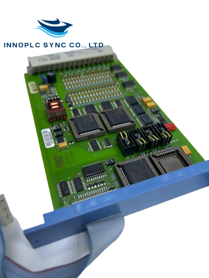
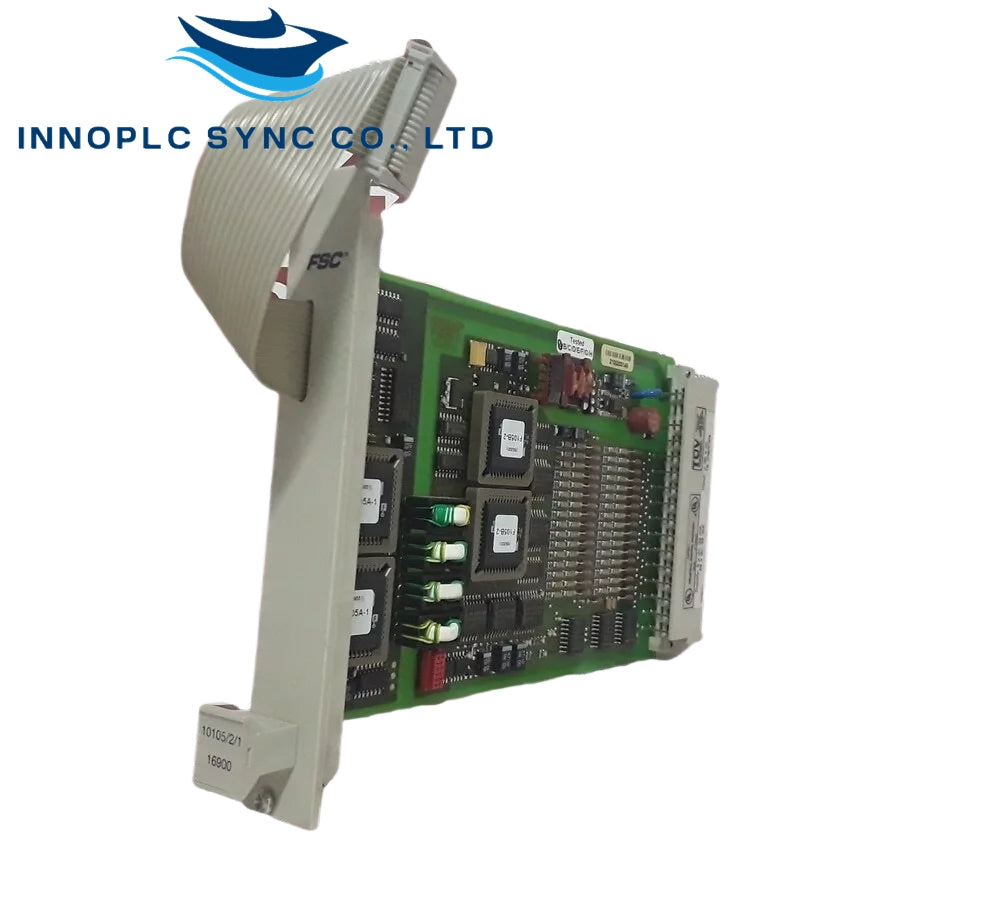
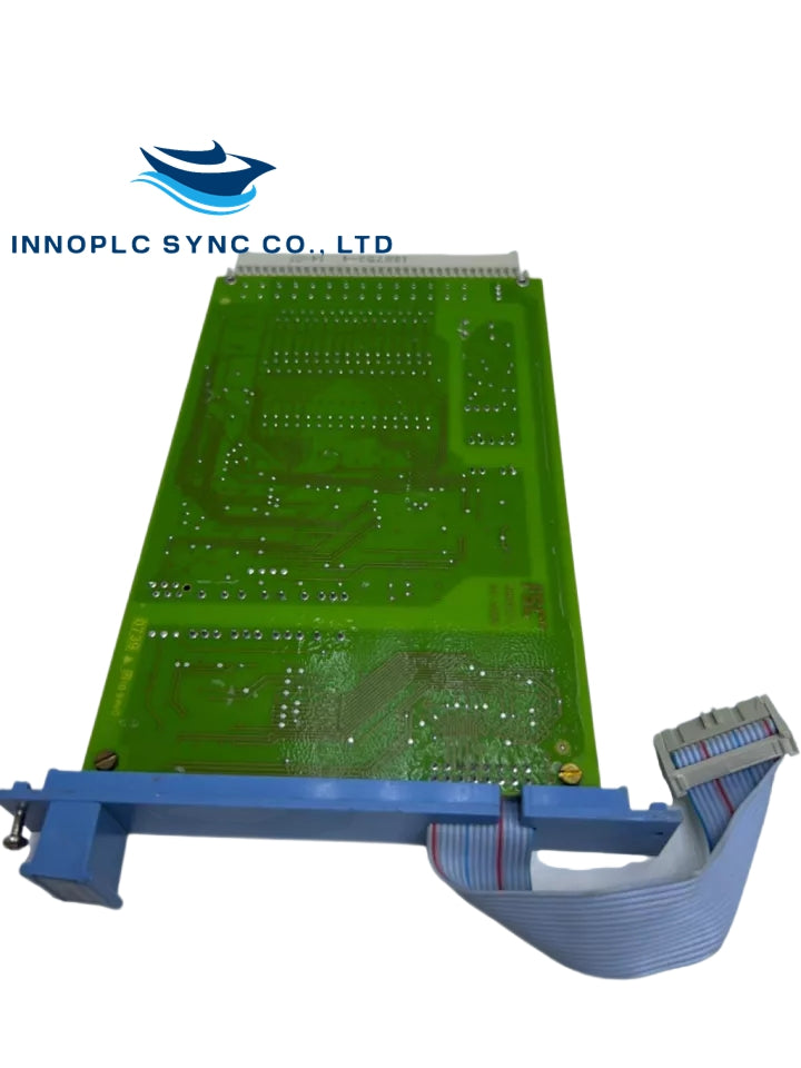
Honeywell 10101/2/1 Fail-Safe Input Module
The Honeywell 10101/2/1, also cataloged as the 10101/2/1 Fail-Safe Digital Input Module, operates as a dedicated hardware component for 24 VDC discrete signal acquisition and safety switch contact monitoring within Honeywell Fail Safe Controller (FSC) and Safety Manager platforms.
Hardware Specifications
| Parameter | Specification |
|---|---|
| Model | 10101/2/1 |
| Brand | Honeywell |
| Origin | Netherlands |
| Weight | 0.2 kg (Shipping Weight: 2 kg) |
| Dimensions | 4 TE, 3 HE (4 HP, 3U Eurocard form factor) |
| Operating Temp | 0 deg C to +60 deg C |
| Logic Power Consumption | 5 VDC at 8 mA (Backplane) |
| Field Power Consumption | 24 VDC int. 110 mA / 24 VDC ext. 110 mA |
| Allowable Power Ripple | < 0.5 Vp-p (0-360 Hz on 5 VDC line) |
| Channel Count | 16 discrete input channels |
| Input Thresholds | HIGH > 15 VDC; LOW < 9 VDC (I < 2 mA) |
| Max Input Voltage | 36 VDC |
| Input Current Nominal | 7 mA at 24 VDC |
| Input Delay Time | Typically 10 ms |
| Firmware Compatibility | Software versions >= 3.00 |
| Approvals & Certifications | CE, TUV, UL |
Process Control & DCS Signal Interfacing
Configured for high-integrity safety loops in Honeywell DCS networks, the assembly conducts continuous hardware self-testing to evaluate logic level 0 detection, logic level 1 detection, and channel-to-channel cross-talk suppression. Galvanic channel-to-channel isolation safeguards the primary system backplane against field-side voltage transients and external ground potential loops. Signal processing circuitry applies a typical 10 ms hardware delay filter to eliminate contact bounce artifacts before mapping status bits to host processor memory.
Frequently Asked Questions
Q: How does the 10101/2/1 module validate channel health during active field operations?
A: Internal diagnostic routines execute automated testing sequences that check the ability to process logic level 0 and logic level 1 states while monitoring input lines to verify cross-talk suppression between adjacent channels.
Q: What power supply parameters are required to maintain stable module operation?
A: The backplane 5 VDC logic rail must draw 8 mA with power supply ripple held below 0.5 Vp-p (0-360 Hz), while field input sensing loops require 24 VDC delivering up to 110 mA from internal or external system distribution lines.
Field Installation Guidelines
Insert the 10101/2/1 Eurocard module into a designated 3U, 4 HP rack slot within the system subrack chassis. Ensure main backplane power is turned off prior to seating the rear edge connectors into the backplane frame to prevent contact pin erosion. Tighten front panel captive mounting screws to establish low-impedance earth grounding to the subrack frame. Route field input wiring using shielded multiconductor cables, keeping discrete input lines separated from AC high-voltage conduits, and terminate cable shields at the cabinet earth bus bar.

