
Honeywell 10105/2/1 Input Module
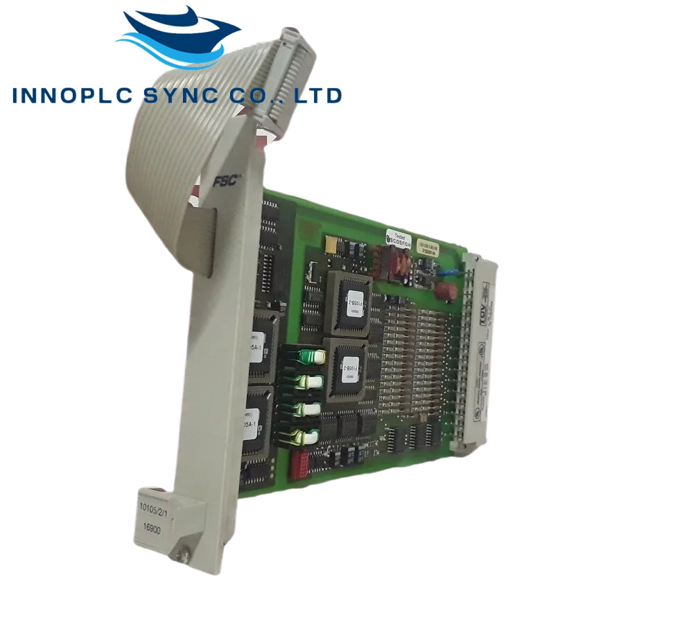
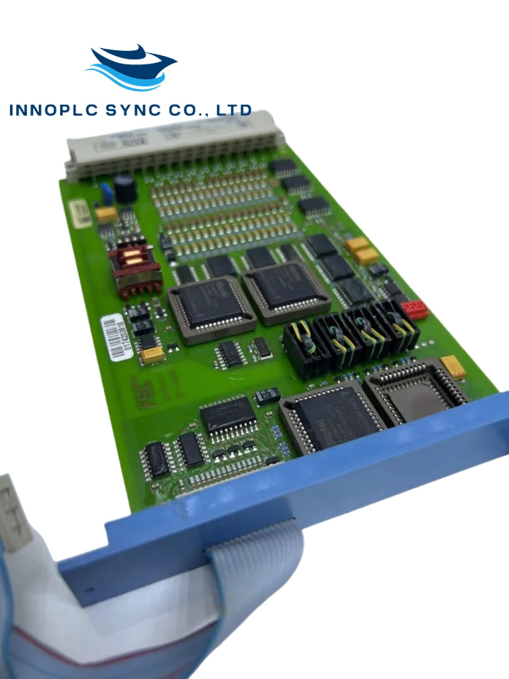
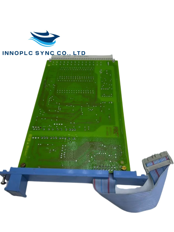
Configured for high-density sensor signal acquisition in Honeywell Fail Safe Controller (FSC) platforms, the Honeywell 10105/2/1 (1010521 Analog Input Module) provides direct physical/electrical execution for 16-channel analog transmitter loop conditioning.
Suffix Breakdown & Model Matrix
The catalog number structure defines specific hardware revision and subsystem parameters:
- Base Part Number (10105): Identifies the core FSC system high-density analog input module platform.
- Variant Qualifier (/2/1): Designates the 16-channel hardware configuration iteration optimized for standard 3U subrack backplane interfaces.
Hardware Specifications
| Parameter | Specification |
|---|---|
| Model | 10105/2/1 |
| Brand | Honeywell |
| Origin | Netherlands |
| Weight | 0.44 lbs (0.20 kg) |
| Dimensions | Standard 3U Eurocard rack form factor |
| Operating Temp | 0 deg C to +60 deg C |
| Power Consumption | Internal rack backplane current draw at 24 VDC |
| Input Channels | 16 analog input channels |
| Channel Isolation | Galvanic isolation between field loops and backplane logic |
4-20 mA HART Loop Protocol & DCS Signal Interfacing
Configured for high-integrity telemetry in Honeywell DCS networks, the assembly conditions 16 analog field input signals before digitizing them for backplane transmission. Channel-to-channel isolation prevents ground loop currents and transient potential differences from corrupting measurement registers. Onboard filter networks attenuate high-frequency industrial noise and cross-talk across adjacent channels, delivering precise process variables to the host controller core.
Frequently Asked Questions
Q: How does the 10105/2/1 module handle out-of-range transmitter signals?
A: When an input signal moves outside standard operating thresholds, diagnostic status flags in the module's status register alert the host CPU to initiate programmed fail-safe routines or signal alarms.
Q: Can the 10105/2/1 module be replaced online while the rack is powered?
A: Module replacement requires verifying system safety constraints and safety manager permissions before hot-swapping to ensure safety loop integrity remains uninterrupted.
Field Installation Guidelines
Mount the 10105/2/1 module into its assigned subrack slot, taking care that the edge connectors line up smoothly with the backplane receptacle. Tighten the front panel retention screws to secure mechanical locking and verify electrical earth grounding to the subrack chassis. Ensure all 16 analog input field cables use shielded twisted-pair wiring, keeping signal lines separate from high-voltage AC conduits, and terminate drain wires at a single dedicated earth bar inside the enclosure.
Honeywell 10105/2/1 Input Module
Honeywell 10105/2/1 Input Module
Configured for high-density sensor signal acquisition in Honeywell Fail Safe Controller (FSC) platforms, the Honeywell 10105/2/1 (1010521 Analog Input Module) provides direct physical/electrical execution for 16-channel analog transmitter loop conditioning.
Suffix Breakdown & Model Matrix
The catalog number structure defines specific hardware revision and subsystem parameters:
- Base Part Number (10105): Identifies the core FSC system high-density analog input module platform.
- Variant Qualifier (/2/1): Designates the 16-channel hardware configuration iteration optimized for standard 3U subrack backplane interfaces.
Hardware Specifications
| Parameter | Specification |
|---|---|
| Model | 10105/2/1 |
| Brand | Honeywell |
| Origin | Netherlands |
| Weight | 0.44 lbs (0.20 kg) |
| Dimensions | Standard 3U Eurocard rack form factor |
| Operating Temp | 0 deg C to +60 deg C |
| Power Consumption | Internal rack backplane current draw at 24 VDC |
| Input Channels | 16 analog input channels |
| Channel Isolation | Galvanic isolation between field loops and backplane logic |
4-20 mA HART Loop Protocol & DCS Signal Interfacing
Configured for high-integrity telemetry in Honeywell DCS networks, the assembly conditions 16 analog field input signals before digitizing them for backplane transmission. Channel-to-channel isolation prevents ground loop currents and transient potential differences from corrupting measurement registers. Onboard filter networks attenuate high-frequency industrial noise and cross-talk across adjacent channels, delivering precise process variables to the host controller core.
Frequently Asked Questions
Q: How does the 10105/2/1 module handle out-of-range transmitter signals?
A: When an input signal moves outside standard operating thresholds, diagnostic status flags in the module's status register alert the host CPU to initiate programmed fail-safe routines or signal alarms.
Q: Can the 10105/2/1 module be replaced online while the rack is powered?
A: Module replacement requires verifying system safety constraints and safety manager permissions before hot-swapping to ensure safety loop integrity remains uninterrupted.
Field Installation Guidelines
Mount the 10105/2/1 module into its assigned subrack slot, taking care that the edge connectors line up smoothly with the backplane receptacle. Tighten the front panel retention screws to secure mechanical locking and verify electrical earth grounding to the subrack chassis. Ensure all 16 analog input field cables use shielded twisted-pair wiring, keeping signal lines separate from high-voltage AC conduits, and terminate drain wires at a single dedicated earth bar inside the enclosure.

