
Honeywell FS-TSDI-1624 Input Module
Configured for high-speed digital signal acquisition in Safety Manager networks, the Honeywell FS-TSDI-1624 (FS-TSDI-1624 digital input module) provides direct physical/electrical execution.
Hardware Specifications
| Parameter | Specification |
|---|---|
| Model | FS-TSDI-1624 |
| Brand | Honeywell |
| Origin | USA |
| Weight | 0.14 kg |
| Dimensions | Standard Safety Manager card format |
| Operating Temp | -20 deg C to +70 deg C |
| Power Consumption | 3.5 W typical |
| Input Channels | 16 optically isolated digital inputs |
| Input Voltage | 24 VDC nominal |
| Isolation | Optical isolation per channel |
| Mounting | DIN rail or rack-mounted |
4-20 mA HART Loop Protocol and Channel Isolation
The module processes discrete field inputs through dedicated optical isolation barriers on every channel, preventing common-mode voltage transients and electrical noise propagation. Strict channel-to-channel isolation safeguards safety instrumented loops against ground potential differences. Continuous diagnostic scanning verifies input voltage thresholds and loop continuity, executing fail-safe state responses immediately if signal anomalies or power supply deviations are detected.
Frequently Asked Questions
Q: Can the module be inserted or removed under active system power?
A: Hot-swapping safety modules requires adherence to proper controller bypass procedures and site authorization protocols to prevent accidental process trips.
Q: How are field wiring errors or open-circuit states detected by the module?
A: The input circuit monitors current draw against established thresholds, asserting a channel fault status flag to the controller upon detecting an open line.
Q: What is the nominal input voltage requirement for active channel triggering?
A: The module expects a 24 VDC nominal input signal from field dry contacts or compatible solid-state sensors.
Field Installation Guidelines
- Mount the module securely onto the designated DIN rail or rack chassis slot, ensuring proper alignment with backplane connectors.
- Terminate field sensor wiring to the appropriate terminal blocks, maintaining correct polarity for all 24 VDC signal circuits.
- Connect shield drain wires from incoming signal cables directly to the designated cabinet earth ground bar.
- Verify input voltage stability and system configuration parameters prior to releasing the safety loop into service.
Honeywell FS-TSDI-1624 Input Module
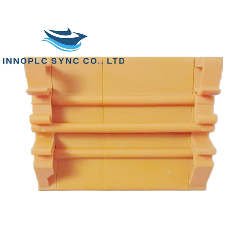
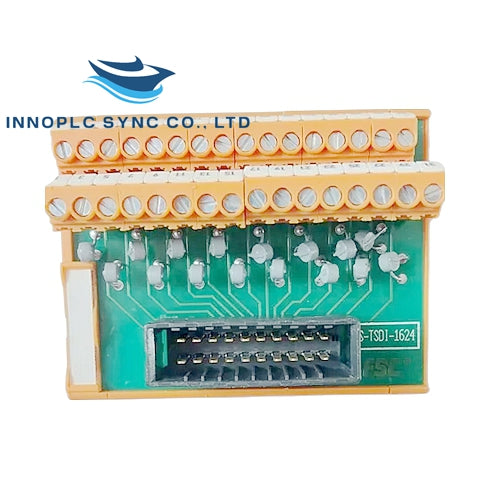
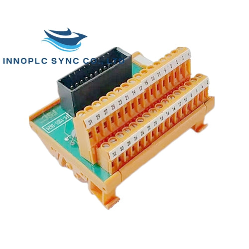
Honeywell FS-TSDI-1624 Input Module
Configured for high-speed digital signal acquisition in Safety Manager networks, the Honeywell FS-TSDI-1624 (FS-TSDI-1624 digital input module) provides direct physical/electrical execution.
Hardware Specifications
| Parameter | Specification |
|---|---|
| Model | FS-TSDI-1624 |
| Brand | Honeywell |
| Origin | USA |
| Weight | 0.14 kg |
| Dimensions | Standard Safety Manager card format |
| Operating Temp | -20 deg C to +70 deg C |
| Power Consumption | 3.5 W typical |
| Input Channels | 16 optically isolated digital inputs |
| Input Voltage | 24 VDC nominal |
| Isolation | Optical isolation per channel |
| Mounting | DIN rail or rack-mounted |
4-20 mA HART Loop Protocol and Channel Isolation
The module processes discrete field inputs through dedicated optical isolation barriers on every channel, preventing common-mode voltage transients and electrical noise propagation. Strict channel-to-channel isolation safeguards safety instrumented loops against ground potential differences. Continuous diagnostic scanning verifies input voltage thresholds and loop continuity, executing fail-safe state responses immediately if signal anomalies or power supply deviations are detected.
Frequently Asked Questions
Q: Can the module be inserted or removed under active system power?
A: Hot-swapping safety modules requires adherence to proper controller bypass procedures and site authorization protocols to prevent accidental process trips.
Q: How are field wiring errors or open-circuit states detected by the module?
A: The input circuit monitors current draw against established thresholds, asserting a channel fault status flag to the controller upon detecting an open line.
Q: What is the nominal input voltage requirement for active channel triggering?
A: The module expects a 24 VDC nominal input signal from field dry contacts or compatible solid-state sensors.
Field Installation Guidelines
- Mount the module securely onto the designated DIN rail or rack chassis slot, ensuring proper alignment with backplane connectors.
- Terminate field sensor wiring to the appropriate terminal blocks, maintaining correct polarity for all 24 VDC signal circuits.
- Connect shield drain wires from incoming signal cables directly to the designated cabinet earth ground bar.
- Verify input voltage stability and system configuration parameters prior to releasing the safety loop into service.

